


A P2 parallel hybrid configuration has been chosen for the IRIZAR vehicle. The parallel architecture consist of an electric machine placed in line with the ICE. It is referred as a parallel configuration because the power is added up from both the ICE and the electric machine to the transmission independent of each other.
Traction System
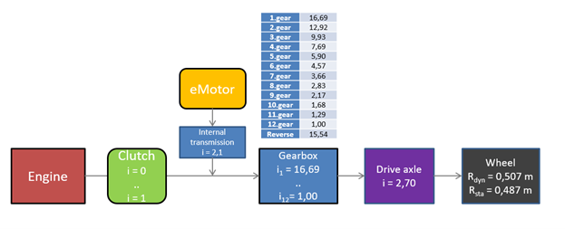
Figure 1: Conceptual architecture of drivetrain with ratios
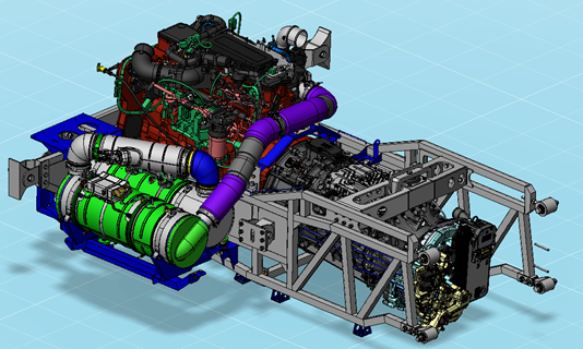
Figure 2: 3D model of ICE with gearbox and electric motor

Figure 3: Real ICE with gearbox and electric motor
A Cummins L9 E6D engine, with 8.9 liters and a 370 hp/ 1600 Nm rating has been integrated in the vehicle. This engine is compatible with both diesel and HVO.
The electric motor is integrated in the hybrid transmission, and it has a peak values of 130 kW and 1180 Nm, and a nominal values of 75 and 420 Nm.
The transmission is an AMT solution, which has 12 speeds with a last direct drive gear. Gear ratios goes from 1:16,69 in first gear to 1:1 in 12 gear. This hybrid package has the clutch and the electric motor integrated in it.
A retarder is also coupled to this transmission.
Energy storage system
The energy storage system is a 650V nominal battery system, with 30,3 kWh and 130 kW peak power. Due to high power/energy needed ratio, LTO cells are used for it.
This system is divided in two different battery pack, integrated at both sides of the vehicle, under the floor.
Auxiliary systems
Air compressor
The air compressor system is a 24V package electrified solution, with an inverter, an electric motor and a compressor attached to this motor.
It has a variable flow capability, with flow between 180 and 450 L/min, working between 1200 and 3100 rpm and 7.5 and 13.5 bar. The power consumption of the system varies between 2.3 and 4.8 kW, depending of the working point.
Front Axle Steering system
The front axle steering system is a 24V package electrified solution, with an inverter, an electric motor and an 8.3 cc hydraulic pump attached to this motor
Cooling system
The final solution consists of two independent cooling systems, each of them with a different radiator-based cooling unit. The cooling capacity of the systems is calculated for a maximum ambient temperature (also known as LAT – limiting ambient temperature) of 41ºC.
Circuit A is dedicated to the engine and transmission, which can operate up to 107ºC. The cooling unit A includes an air/air heat exchanger for the ICE intercooler system, and a water/air heat exchanger for the engine and transmission together. It also includes seven electric fans to guarantee enough airflow in the most demanding situations. Additionally, an electric pump is included in the circuit A to guarantee the required flow in the fully electric mode.
Circuit B is connected to the power electronics and air compressor, and must not exceed 65ºC. This circuit is propelled exclusively by an electric pump. The radiator B is composed by a water/air heat exchanger and two additional electric fans.
A 3.5kW cooling power battery thermal management system has been integrated in the vehicle, in order to cool down the batteries even if worst scenario conditions.
Energy Management/ advanced HCM control module
One is trying to avoid bad efficiency working points of the ICE, to maximize the use of the eMotor in positive torque and to try to recuperate as much energy as possible during braking.
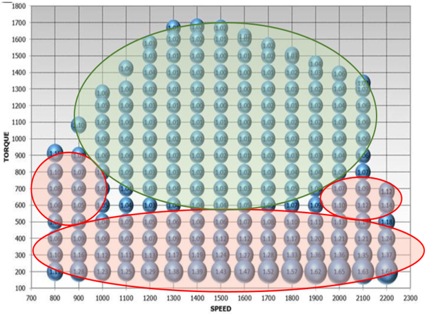
Figure 4 Speed vs Torque
Significant results in this respect are:
1.Electric mode
ICE Off, only eMotor (up to 10-15 km).
Manually / automatically engaged (only low speed).
2.Hybrid mode
Torque split ICE/eMotor.
Sub-modes: Normal, charge, save (SOC% target change).
3.Boost
Demanded torque > ICE Max torque.
Special torque split ICE/eMotor.
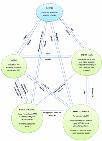
Figure 5 Modes