


CO2 emissions reduction from transport sector is of paramount importance to achieve internationally agreed objectives established in the recent Paris Agreement COP21. An increasing amount of research is being focused on improving the efficiency of existing internal combustion engines and on the introduction of alternative fuels. In the collaborative European project LONGRUN, several innovative solutions are under investigation to reduce CO2 emissions from heavy duty vehicles.
IFP Energies Nouvelles (IFPEN) is working on high fidelity 3D simulation tools to reduce heat loss through the application of thermal barrier coatings and to introduce alternative fuels, such as H2 and Methanol. The scheme (Fig.1), shown below, illustrates the three different research axes in which IFPEN is integrated. In the first phase, experimental measurements data are provided by FEV for numerical model validation. Then, in the second phase, useful feedback, coming from numerical simulation, is used for further improvement of the developed prototype.
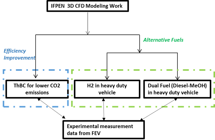
Figure 1: Illustration of three different research axes in which IFPEN is integrated.
Thermal barrier coating for lower CO2 emissions
For heavy duty compression ignited ICEs, one of the multiple paths towards improving overall performances and therefore lower CO2 emissions is to reduce heat losses. To accomplish this objective, IFPEN and FEV are working together on a methodology which consists in applying thermal barrier coatings on different parts of the combustion chamber. In the frame of the LONGRUN program, the analysis is focused on the effects observed when coating the engine piston since the latter is responsible for 50% of the total heat losses during the engine cycle.
To ensure the best accuracy and understanding of the physics, experimental results, coming from FEV test benches together with precise materials definitions supplied by Tenneco, are plugged into IFPENs latest models and methodologies. The injection, combustion and conduction parts of the 3D CHT computations are solved using the CONVERGE CFD software using a weak coupling methodology between the fluid and solid phases.
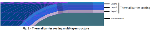
IFPEN is developing an innovative approach in which, for the thermal barrier coating, real properties are being considered. The thickness of ~200 µm is meshed accordingly in the 3D model and in addition, a real multi-layered structure (Fig. 2) with different thermal properties per layer is also integrated in the 3D CHT simulations.
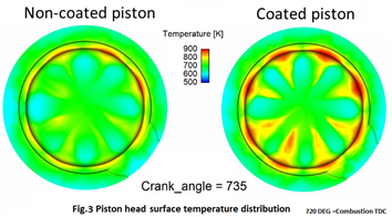
Engaging its prior experience in the domain, IFPEN has obtained promising results which capture the effects of multi-layered thermal barrier coatings. (Fig. 3)
In parallel with the methodology development, FEV and IFPEN are elaborating an experimental protocol for the simulation results validation.
H2 in heavy duty vehicles
CFD numerical simulations were conducted at IFPEN for the configuration of a 2L swept volume HD single cylinder proposed by FEV. The H2 study focuses on two main objectives:
- Investigate the in-cylinder mixture formation comparing several injection strategies in terms of Start of Injection (SOI) and injection cap design. The study will help FEV to find and control the optimal injection parameters that will improve the H2-Air mixture quality to control NOx emissions and prevent combustion anomalies on the test-bench.
- Validate IFPEN CFD tools for prediction of ignition, flame propagation and knocking in H2 spark ignition engines.
Achievements
With a first single central hole injector, an optimal SOI was found at -180° (intake valve closure) before the combustion top dead center. This injection timing gives an optimal compromise between the in-cylinder air filling and the mixture formation at specified spark timing, as shown in Fig. 4.
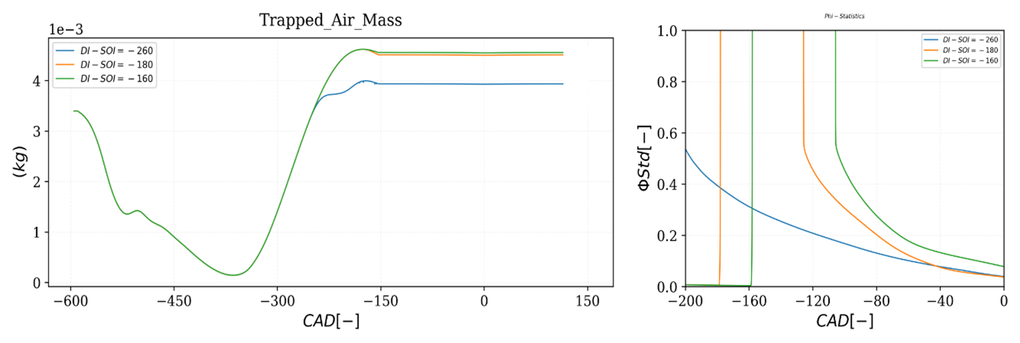
Figure 4:
Left: evolution of the in-cylinder air trapped mass during the engine cycle.
Right: evolution of the standard deviation for the in-cylinder equivalence ratio mass weighted distribution. SOI = (-260, -180, -160).
A comparison with an alternative multi-hole injector cap design was also carried-on in the numerical study. This design choice reduces the risk of creating rich mixture regions close to the exhaust valves at specified spark timing. The IFPEN CFD turbulent combustion modelling approach has been challenged on a PFI operating point provided by FEV (1200 rpm/IMEP = 10 bar). The ignition and flame propagation models were validated on ignition and equivalence ratio sweeps up to knocking conditions. The CFD turbulent combustion model allows to retrieve knocking tendencies as in the experimental study (Fig. 5). According to the numerical simulations, in the region close to the exhaust valve, auto-ignition points are observed which can be the origin of the experimental detected knocking.
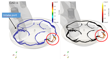
Figure 5: Auto-Ignition flame index and auto-ignition progress variable visualized on a temperature (1800 K) iso-surface.
Dual fuel strategy and application of methanol in heavy duty ICE
A direct injection dual fuel strategy which primarily uses methanol as the main fuel and diesel in small quantity as pilot injection is being investigated in the collaborative project LONGRUN. Given the thermal characteristic of methanol, existing diesel fuel engine can be easily adapted for its use. Use of methanol in ICE offers several advantages. It has zero sulfur and hence doesn’t produce SO2 and SO3. It has higher auto-ignition temperature and hence higher compression ratio can be used – increasing the thermal efficiency. Fuels without carbon to carbon bonds inherently demonstrate very low levels of particulates. Methanol’s combustion produces lower emissions and noise than diesel. Because of presence of inherent oxygen in its molecular structure (roughly 50 % of oxygen by weight), it favors more complete combustion producing less CO and particulates. Its combustion produces less CO by easily converting them into a CO2. Production of NOx sees two competing phenomena occurring: availability of extra O2 allows possibility of high EGR and hence lowers combustion temperature; but higher permissible compression ration can increase temperature in the cylinder. So at same compression ratio as a diesel engine use of methanol can significantly reduce NOx production. Because of its high auto-ignition temperature it is safe to handle, unlike some of other alternative fuels such as H2 it doesn’t require strict safety requirement. Above all it can be manufactured, at lower cost (half the cost of diesel [4]), from a variety of abundantly available renewable and non- renewable resources.
IFPEN is currently conducting 3D simulations to understand the in-cylinder underlying phenomena and help optimize the direct injection dual fuel strategy. Both fuels are directly injected into the combustion chamber. Small quantity of diesel is injected as pilot injection to start the combustion. After that the main fuel methanol is injected. The injection configuration is shown in Figure 6 below.
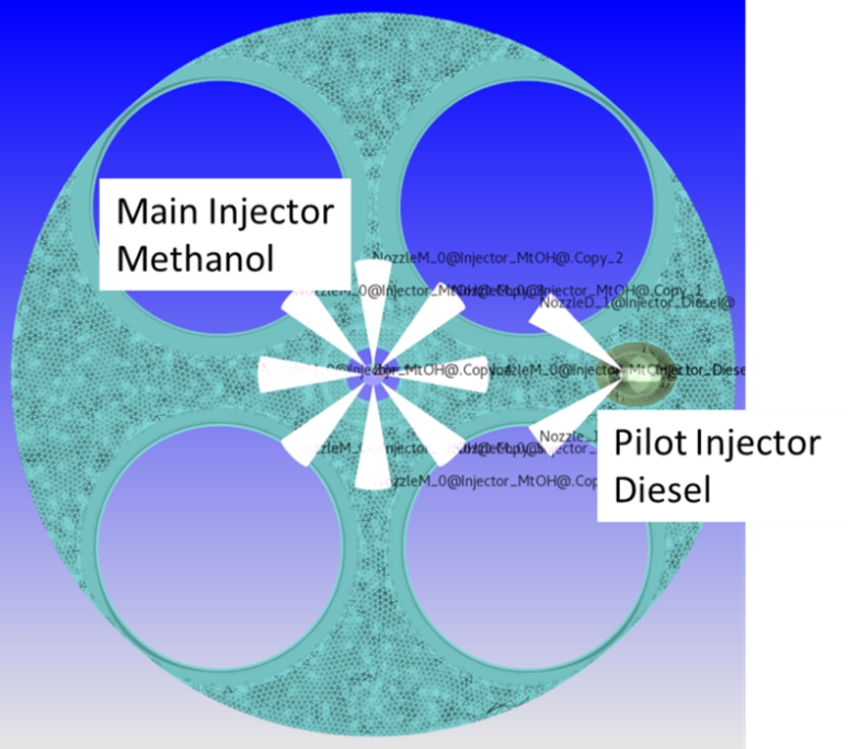
Figure 6: Orientation of two injectors
First of its kind, dual fuel diffusion combustion is being modelled by 3-Zones Extended Coherent Flame Model (ECFM-3Z)[1] combustion model developed at IFPEN and commonly used in the industry. Auto-Ignition was modelled by Tabulated Kinetics Ignition (TKI) Tabulation method [2]. TKI tables were constructed using a well validated and detailed kinetic mechanism from LLNL[3]. First combustion result is shown in Figure 7. Figure 7 (a) shows comparison of experimental and simulation cylinder pressure. Figure 7 (b) shows pilot injection of diesel and consequent start of the combustion. Further ahead, we see injection of the methanol on the right side of the Figure 7 (c). Combustion calibration with FEV provided data is on-going. Once validated, the 3D simulations will provide important insight into the injection and combustion strategy of this dual fuel strategy.

Figure 7: Combustion – (a) Comparison of experimental and simulation cylinder pressure; (bt) start of combustion with pilot injection of diesel which is then continued by (c) methanol injection.
References:
1. O. Colin, A. Benkenida. The 3-Zones Extended Coherent Flame Model (Ecfm3z) for Computing Premixed/Diffusion Combustion. Oil & Gas Science and Technology – Revue d’IFP Energies nouvelles, Institut Français du Pétrole, 2004, 59 (6), pp.593-609. ff10.2516/ogst:2004043ff. ffhal-02017326f.
2. Colin O., Pires da Cruz A., and Jay S.. Detailed chemistry-based auto-ignition model including low temperature phenomena applied to 3-D engine calculations. Proceedings of the Combustion Institute, 30:2649–2656, 2005.
3. M. Mehl, w.j. Pitz, c.k. Westbrook, h.j. Curran. Kinetic modeling of gasoline surrogate components and mixtures under engine conditions
4. The Methanol Institute – http://www.methanol.org/wp-content/uploads/2020/04/Dor-Methanol-Economy-June-2017.pdf